# Labs
# Lab 02 - Resistors
### Overview
In this Lab, we will be building basic resistor circuits and measuring the changes in voltage and current that occur when resistances change within a circuit.
### Basic Circuits
1. Locate the resistors in the table and record the following values.
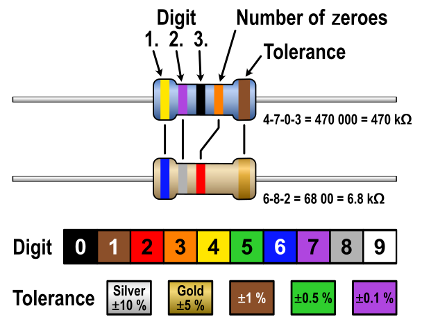
This is the resistor color code. It is used to identify the value of a given resistor, based on the colors in order. The resistors we will use in lab are all three band, to identify them, look for the gold tolerance band, then, starting from the opposite side, the bands will be, in order, the first digit, the second digit (as in 1 is the first digit and 0 is the second, making 10) then the third will be the number of zeros following. Thus, brown black brown would be 100 ohms.
### Definitions
**Open Circuit:** There is no connection. The resistance is infinite.
[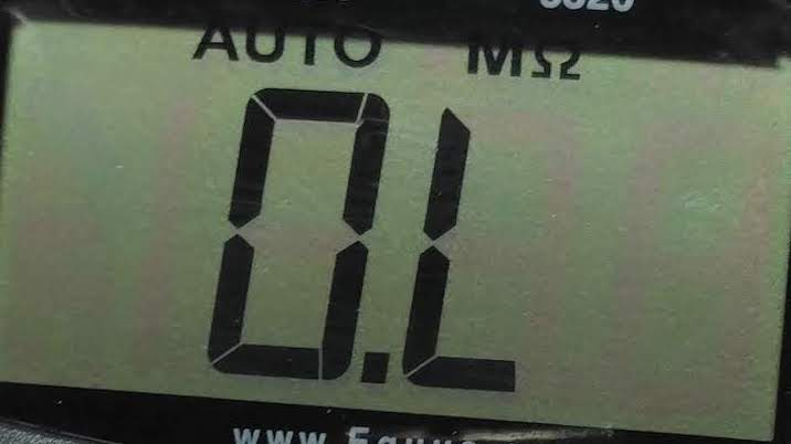](https://cset2.stcc.edu/bookstack/uploads/images/gallery/2025-02/Hs3X4joBZ15PQEtV-image.png)
**Closed Circuit:** There is a connection with no or negligible resistance. The value is approximately zero.
5.) Given the color codes in the table below determine the nominal resistance value of the resistor. The nominal value is the ideal value. You can ignore the tolerance.
| **Component**
| **1st**
| **2nd**
| **3rd**
| **Tolerance**
| **Value**
|
| R1 | Brown
| Black
| Brown
| Gold
|
|
| R2
| Brown
| Black
| Red
| Gold
|
|
| R3
| Brown
| Black
| Orange
| Gold |
|
| R4
| Orange
| Orange
| Brown
| Gold |
|
| R5
| Yellow
| Violet
| Brown
| Gold |
|
| R6
| Yellow
| Violet
| Red
| Gold |
|
| R7
| Brown | Black
| Yellow
| Gold |
|
| R8
| Orange
| Orange
| Red
| Gold |
|
5.) We will be using an arduino's 5v rail as a power source and two resistors. The resistors are labeled R1 and R2.
### Power Conventions
Use a red wire for the positive terminal of the power supply.
Use a black wire for the ground. Any ground will suffice. The blue line at the bottom is the ground rail. Any connection to this rail connects to the power supply ground.
### Resistor Layout
The top resistor is R1. It connects from the 9V power supply to R2.
The bottom resistor is R2. It connects from the bottom of R1 to ground on the power source.
### Classical Current Flow
Current leaves the battery or power supply from the positive terminal, passes through the circuit, and then returns to the battery or power supply to the negative terminal. A complete circuit is necessary for current to flow.
### Schematic diagram for Test Circuit 1
[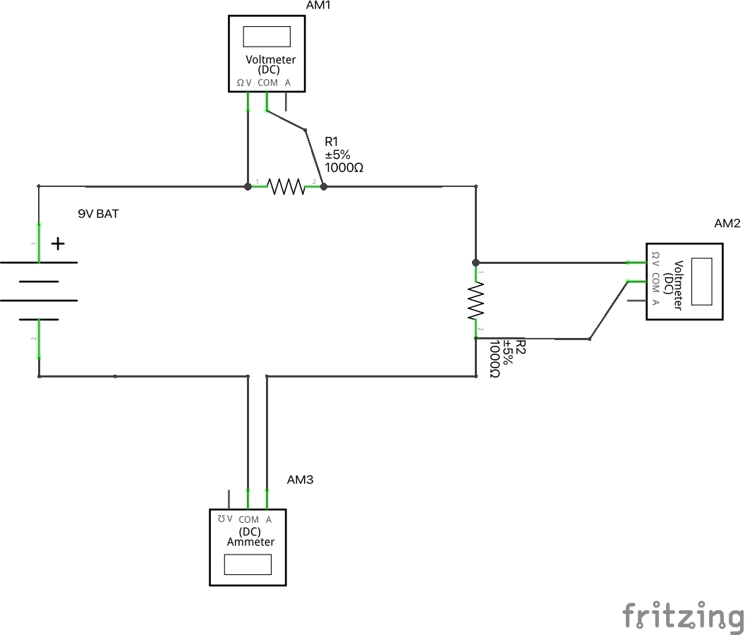](https://cset2.stcc.edu/bookstack/uploads/images/gallery/2025-02/8sdVJLhkla1vn57O-image.png)
### Explanation
The 9V battery is connected to resistor R1 and then resistor R2 which is then connected back to the negative or ground terminal. Volt meter AM1 measures the voltage across R1. Volt meter AM2 measures the voltage across R2. Ammeter AM3 is connected in series between R2 and the ground terminal to measure the current in the circuit. The current leaving the battery, going through R1, then going through R2 returns to the battery through the negative terminal.
### A Physical Diagram of the Test Circuit
[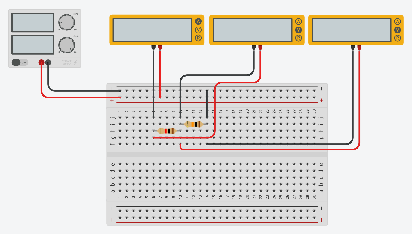](https://cset2.stcc.edu/bookstack/uploads/images/gallery/2025-02/majz6UUSnQDGPBuJ-image.png)
R1 is in series with R2. There is only one path for the current to flow through the circuit. So, Itotal = Ibattery = IR1 = IR2.
### A Simpler Schematic Diagram of the Circuit.
[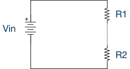](https://cset2.stcc.edu/bookstack/uploads/images/gallery/2025-02/vQCp3xeLUaoNUKDD-image.png)
6.) Take all the measurements in Tinkercad and fill in the table. R1 remains the same in all cases. Change the value of R2 with each resistor from the table in turn. Record the measurements, and fill in the table.
If you have not already done so watch the video for the lab, create the circuit, and simulate the circuit for each of the R2 resistor values below.
| R1
| R2
| Vin
| VR1
| VR2
| VR1 + VR2
| It
|
| 1000Ω
| 1000Ω | 5v
|
|
|
|
|
| 1000Ω | 100Ω | 5v |
|
|
|
|
| 1000Ω | 470Ω | 5v |
|
|
|
|
| 1000Ω | 3.3KΩ | 5v |
|
|
|
|
| 1000Ω | 4.7KΩ | 5v |
|
|
|
|
| 1000Ω | 10KΩ | 5v |
|
|
|
|
| 1000Ω | 100KΩ | 5v |
|
|
|
|
Notes:
1000 Ω = 1K Ω
4700 Ω = 4.7K Ω
10000 Ω = 10K Ω
100000 Ω = 100K Ω
7.) Accuracy check of the measurements in your table. Add VR1 to VR2 and place the result in the last column. The sum of these voltages should equal the supply voltage.
8.) Save your Tinkercad circuit under the name “ELE111 Circuit Lab 1.
# Lab 03 - Intro to the Arduino IDE
### Intro
In this lab, we are going to be using the Arduino IDE for the first time. The Arduino IDE is the piece of software responsible for translating the code you write into machine code that the microcontroller can understand (this function by itself is called the compiler) and then uploading it to your arduino, so that your program can actually run (called "flashing" the arduino).
### Installation
**THIS STEP IS ONLY FOR YOUR OWN COMPUTER, THE LAB COMPUTERS ALREADY HAVE THE ARDUINO IDE PREINSTALLED.**
The installer for the arduino IDE is located at : [https://www.arduino.cc/en/software](https://www.arduino.cc/en/software)
On first run, the IDE will look like this:
[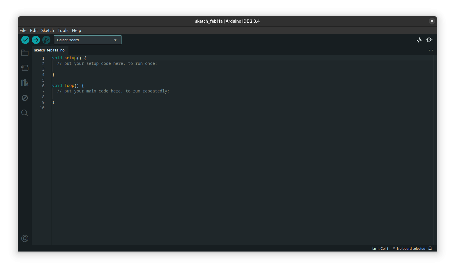](https://cset2.stcc.edu/bookstack/uploads/images/gallery/2025-02/exbJQx08dzUW7O5n-image.png)Once installed, download the SIK.zip file, located on blackboard, and install it into the IDE using Sketch>Include Library>Add a .zip library, here:
[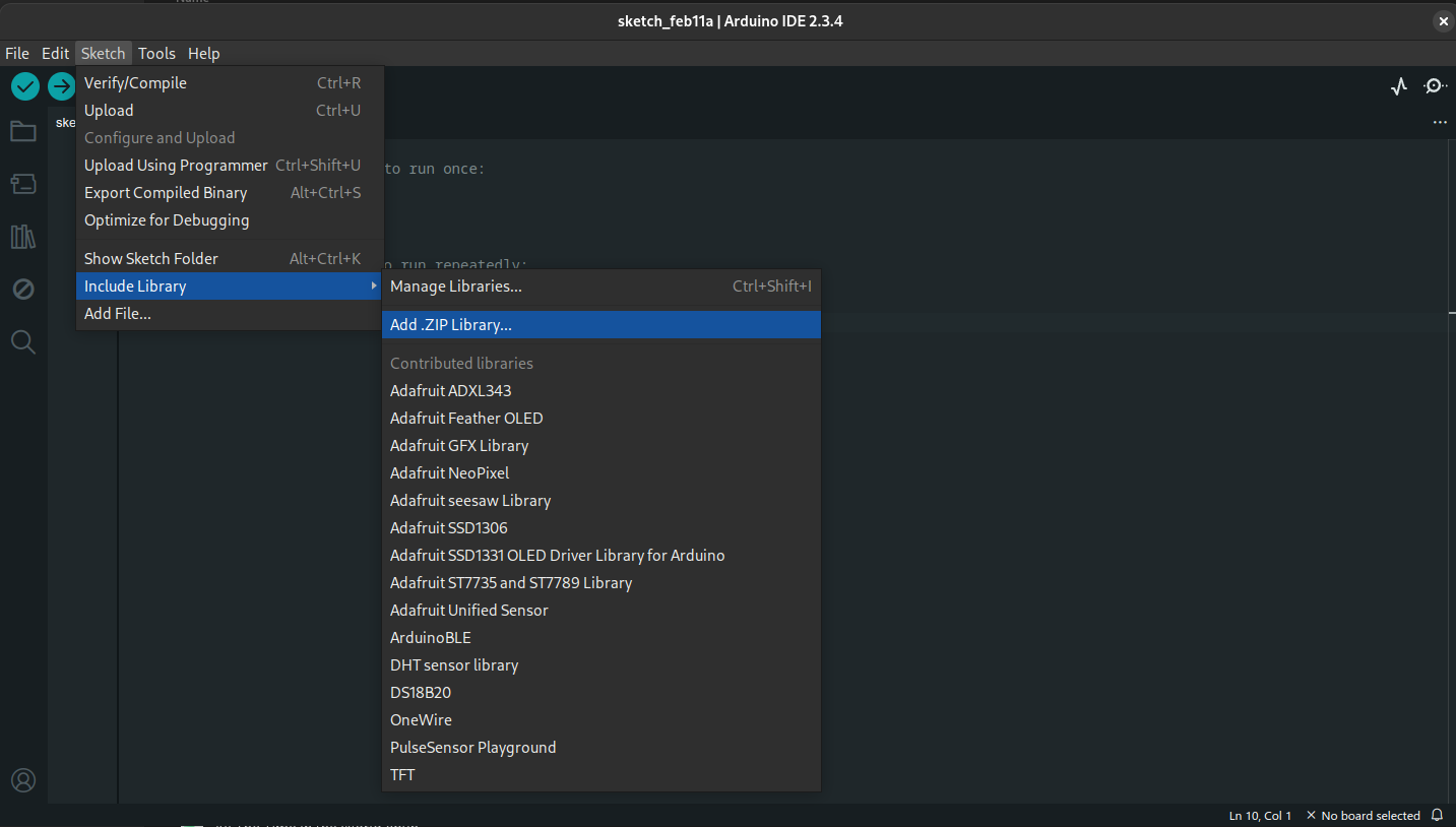](https://cset2.stcc.edu/bookstack/uploads/images/gallery/2025-02/yqEyDGrsutqURCvo-image.png)
this will add the examples into File>Examples>Sparkfun Inventors Kit.
### Connecting your Arduino
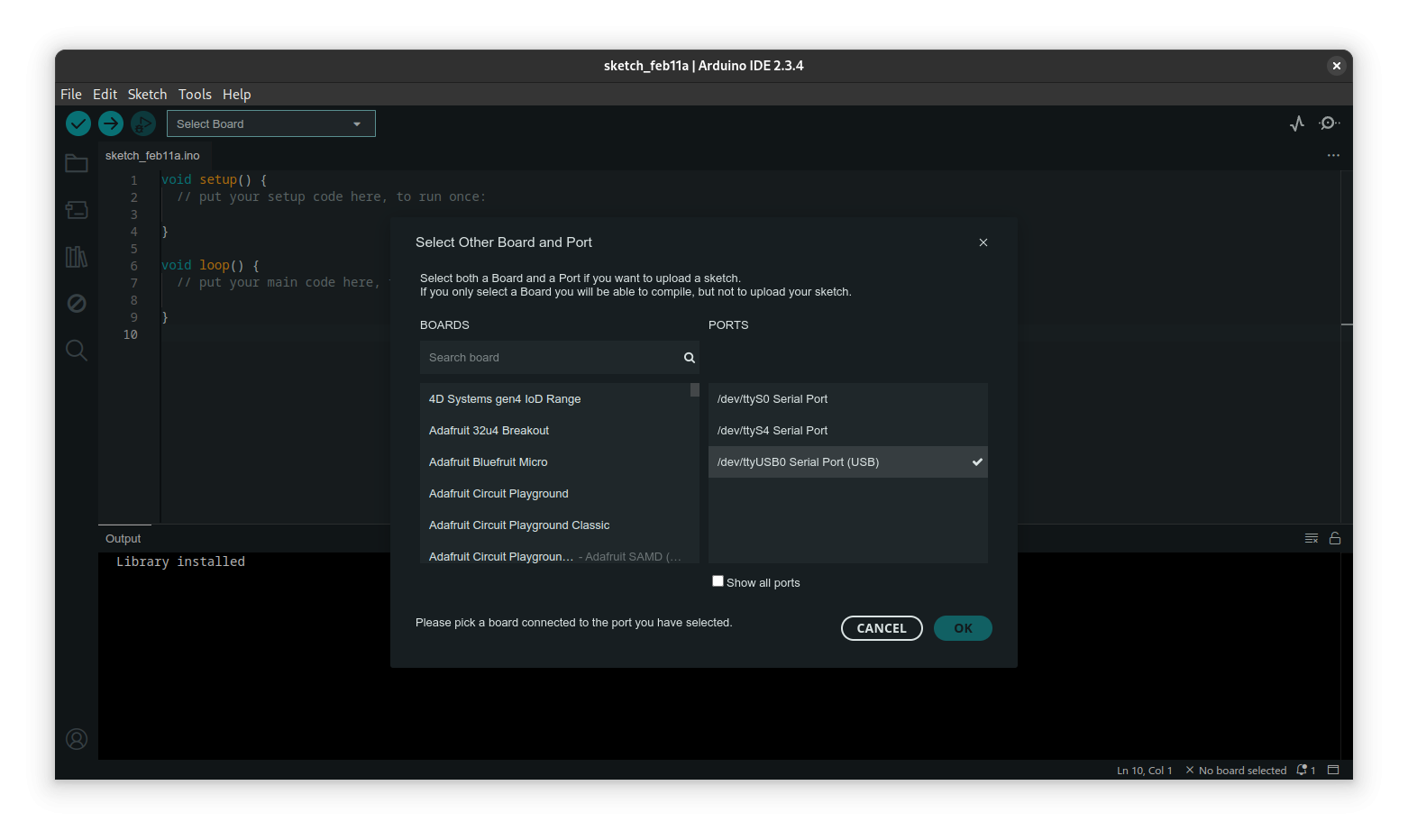
When you connect your arduino to usb, it may be detect in the "Select Board" dropdown automatically (it would say something other than "Select Board"), if it isn't:
[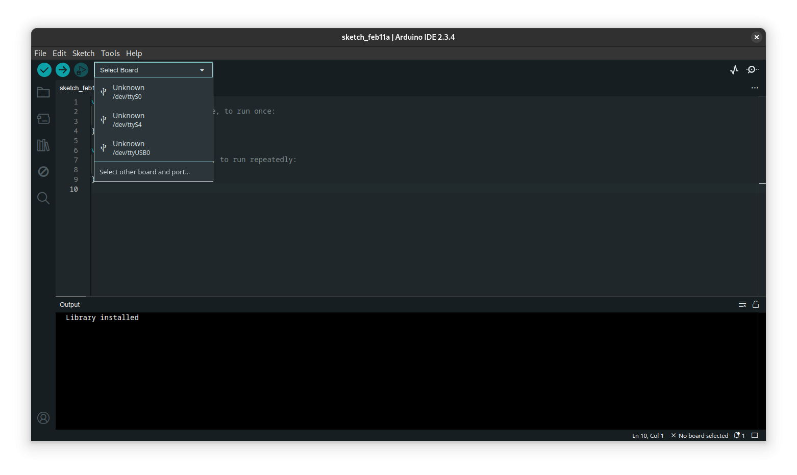](https://cset2.stcc.edu/bookstack/uploads/images/gallery/2025-02/DYmlShoRfCesuJBR-image.png)
open the menu, and select the last Port in the list (on linux it will be /dev/ttyUSB0, on windows it will likely be COM4 or higher) this will open the following menu:
[](https://cset2.stcc.edu/bookstack/uploads/images/gallery/2025-02/lRLkoaf1cPTwMBkW-image.png)
In the "Search Board" field type in Uno, and select Arduino Uno from the results:
[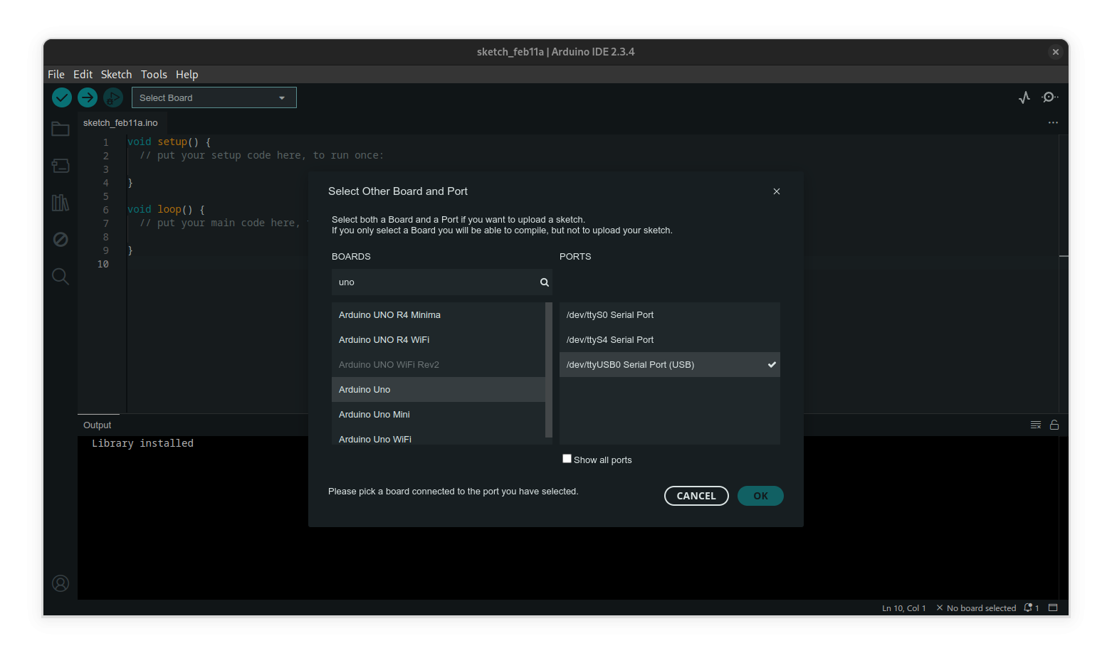](https://cset2.stcc.edu/bookstack/uploads/images/gallery/2025-02/WWHJm27RRtn9sccD-image.png)
Now, select File>Examples>01 Basics>Blink which will open the following program:
[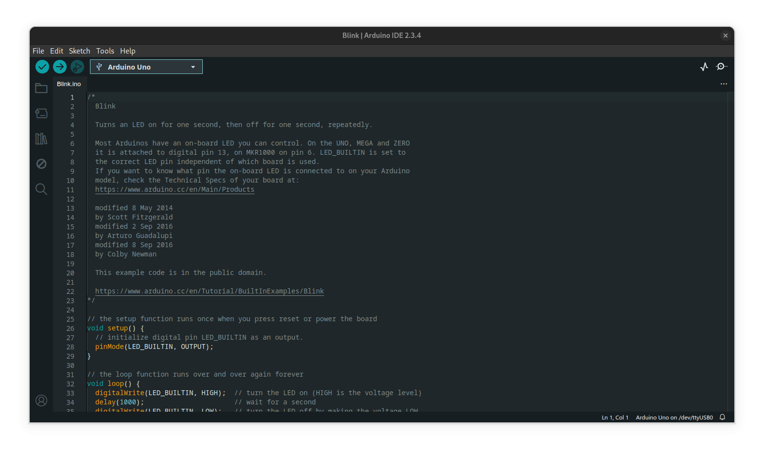](https://cset2.stcc.edu/bookstack/uploads/images/gallery/2025-02/n7DLBXlU4oH1wGVR-image.png)
click the upload arrow in the top left next to the checkmark, and wait a few seconds for the program to be uploaded to your Arduino. When done, you should see the led labeled 13 on the Arduino blinking on and off once per second. Congratulations! You've just written your first program to an Arduino!.
# Lab 03 - Using LED's with an Arduino
In this lab, we will be learning how to control simple digital circuits using a microcontroller. The micro we will be using is called an atmega328p, and it is embedded in a development board called an Arduino.
[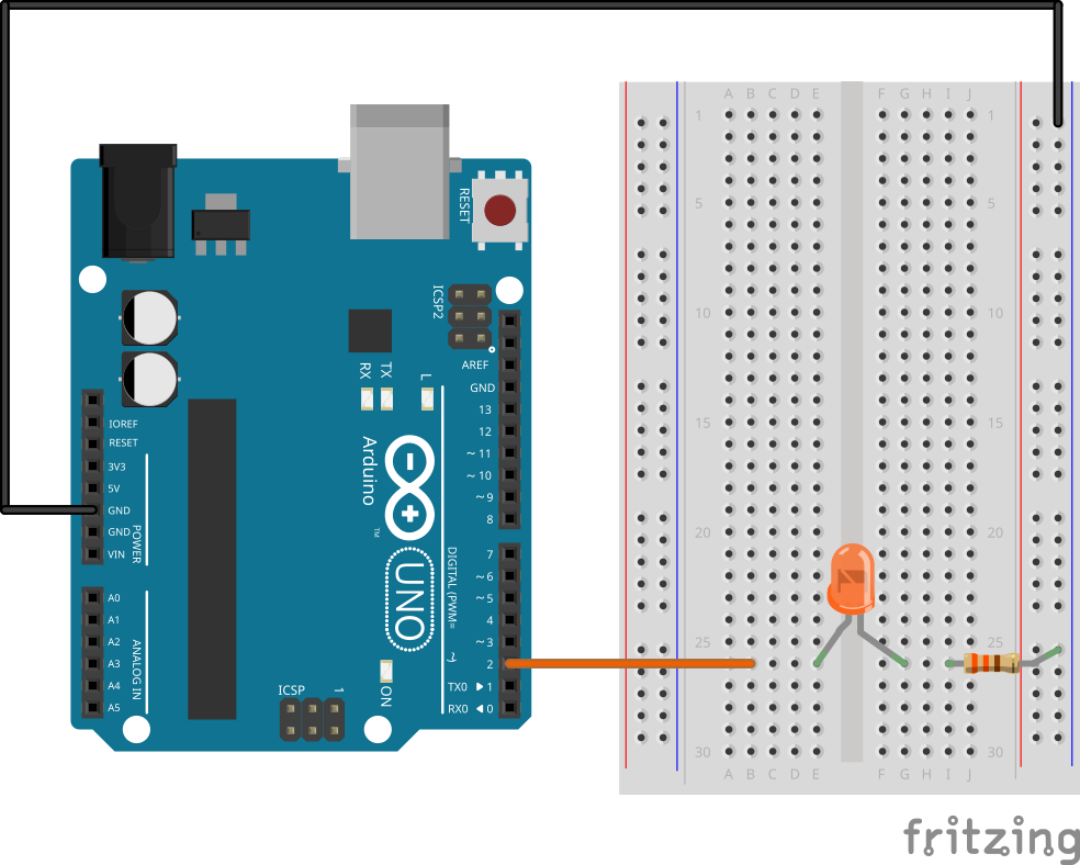](https://cset2.stcc.edu/bookstack/uploads/images/gallery/2024-10/81YTFH8SCXyWmk1d-figure-1-single-led.png)
```c
int ledPin = 2;
void setup() {
pinMode(ledPin, OUTPUT);
}
void loop() {
digitalWrite(ledPin, HIGH);
delay(1000);
digitalWrite(ledPin, LOW);
delay(1000);
}
```
```c
int ledPin2 = 2;
int ledPin3 = 3;
int ledPin4 = 4;
void setup() {
pinMode(ledPin2, OUTPUT);
pinMode(ledPin3, OUTPUT);
pinMode(ledPin4, OUTPUT);
}
void loop() {
digitalWrite(ledPin2, HIGH);
digitalWrite(ledPin3, HIGH);
digitalWrite(ledPin4, HIGH);
delay(1000);
digitalWrite(ledPin2, LOW);
digitalWrite(ledPin3, LOW);
digitalWrite(ledPin4, LOW);
delay(1000);
}
```
```c
int ledPin2 = 2;
int ledPin3 = 3;
int ledPin4 = 4;
void setup() {
pinMode(ledPin2, OUTPUT);
pinMode(ledPin3, OUTPUT);
pinMode(ledPin4, OUTPUT);
}
void loop() {
digitalWrite(ledPin2, HIGH);
digitalWrite(ledPin3, LOW);
digitalWrite(ledPin4, LOW);
delay(1000);
digitalWrite(ledPin2, LOW);
digitalWrite(ledPin3, HIGH);
digitalWrite(ledPin4, LOW);
delay(1000);
digitalWrite(ledPin2, LOW);
digitalWrite(ledPin3, LOW);
digitalWrite(ledPin4, HIGH);
delay(1000);
}
```