Lab 02 - Resistor Measurement
Overview
In this Lab, we will be building basic resistor circuits and measuring the
Basic Circuits
-
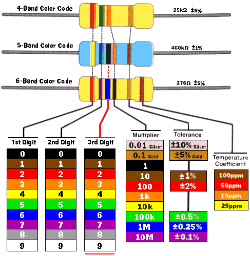
Locate the resistors in the table and record the following values.
See the resistor color code guide at http://www.instructables.com/id/Resistor-Color-Code-Guide/
The image from this website is listed here for your convenience. List the color codes in the table when you take the measurements.
Definitions
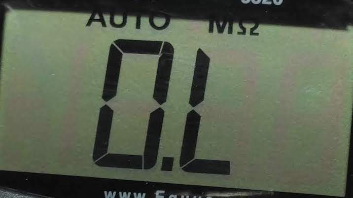
Open Circuit: There is no connection. The resistance is infinite.
Closed Circuit: There is a connection with no or negligible resistance. The value is approximately zero.
5.) Given the color codes in the table below determine the nominal resistance value of the resistor. The nominal value is the ideal value. You can ignore the tolerance.
| Component |
1st |
2nd |
3rd |
Tolerance |
Value |
| R1 | Brown |
Black |
Brown |
Gold |
|
| R2 |
Brown |
Black |
Red |
Gold |
|
| R3 |
Brown |
Black |
Orange |
Gold | |
| R4 |
Orange |
Orange |
Brown |
Gold | |
| R5 |
Yellow |
Violet |
Brown |
Gold | |
| R6 |
Yellow |
Violet |
Red |
Gold | |
| R7 |
Brown | Black |
Yellow |
Gold | |
| R8 |
Orange |
Orange |
Red |
Gold |
5.) We will be using an arduino's 5v rail as a power source and two resistors. The resistors are labeled R1 and R2.
Power Conventions
Use a red wire for the positive terminal of the power supply.
Use a black wire for the ground. Any ground will suffice. The blue line at the bottom is the ground rail. Any connection to this rail connects to the power supply ground.
Resistor Layout
The top resistor is R1. It connects from the 9V power supply to R2.
The bottom resistor is R2. It connects from the bottom of R1 to ground on the power source.
Classical Current Flow
Current leaves the battery or power supply from the positive terminal, passes through the circuit, and then returns to the battery or power supply to the negative terminal. A complete circuit is necessary for current to flow.
Schematic diagram for Test Circuit 1

Explanation
The 9V battery is connected to resistor R1 and then resistor R2 which is then connected back to the negative or ground terminal. Volt meter AM1 measures the voltage across R1. Volt meter AM2 measures the voltage across R2. Ammeter AM3 is connected in series between R2 and the ground terminal to measure the current in the circuit. The current leaving the battery, going through R1, then going through R2 returns to the battery through the negative terminal.
A Physical Diagram of the Test Circuit
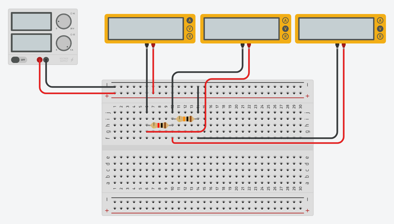
R1 is in series with R2. There is only one path for the current to flow through the circuit. So, Itotal = Ibattery = IR1 = IR2.
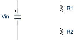
A Simpler Schematic Diagram of the Circuit.
6.) Take all the measurements in Tinkercad and fill in the table. R1 remains the same in all cases. Change the value of R2 with each resistor from the table in turn. Record the measurements, and fill in the table.
If you have not already done so watch the video for the lab, create the circuit, and simulate the circuit for each of the R2 resistor values below.
| R1 |
R2 |
Vin |
VR1 |
VR2 |
VR1 + VR2 |
It |
| 1000Ω |
1000Ω | 5v |
||||
| 1000Ω | 100Ω | 5v | ||||
| 1000Ω | 470Ω | 5v | ||||
| 1000Ω | 3.3KΩ | 5v | ||||
| 1000Ω | 4.7KΩ | 5v | ||||
| 1000Ω | 10KΩ | 5v | ||||
| 1000Ω | 100KΩ | 5v |
Notes:
1000 Ω = 1K Ω
4700 Ω = 4.7K Ω
10000 Ω = 10K Ω
100000 Ω = 100K Ω
7.) Accuracy check of the measurements in your table. Add VR1 to VR2 and place the result in the last column. The sum of these voltages should equal the supply voltage.
8.) Save your Tinkercad circuit under the name “ELE111 Circuit Lab 1.